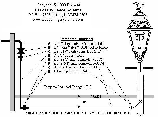
Gaslite Installation Kit Instructions

(CHECK LOCAL CODES BEFORE INSTALLING)
1. Install 1/4" 90 degree elbow ( A ) on source (not included)
2. Screw shut -off valve ( B ) into 1/4 " 90 degree elbow ( A ).
3. Screw 1/4" MPH x 3/8" adapter ( C ) into valve.
4. Dig or slit trench (10" deep) to gaslite location for Gasflex tubing ( G ).
5. Slip copper tubing ( D ) into ( C ) fitting and curve copper tubing to conform to trench.
6. Connect 3/8" copper to 3/8" Gasflex tubing using 3/8" union connector ( E ).
- Install copper tubing into compression nut.
- Seat tube support ( H ) into Gasflex tube.
- Install Gasflex tubing into other end of compression fitting.
- Push tubing all the way into compression fitting before tightening nuts.
7. Assemble gaslite per instructions in carton. Cut flare of copper tubing at base of post and
remove flare nut. If there is a female thread in valve of gaslite, install 1/8" x 1/4" P4MC2
adapter (not supplied in kit).
8. After posthole is dug, set post in, pour cement and level (do not cover tubing hole on side of post.
9. Connect 3/8" Gasflex to 1/4" copper tubing using union connector ( F ).
- Install copper tubing into compression nut.
- Cut Gasflex tubing to proper length.
- Seat tube support ( H ) into Gasflex tubing.
- Install Gasflex tubing into other end of compression fitting.
- Push tubing all the way into compression fitting before tightening nuts.
- Tighten all fittings, turn on gas supply at source and open valve at gaslite,
and bleed off air in gaslite line. Then turn valve off at gaslite and soap test
all the connections.
- Paint copper tube from 6" above grade to connection to Gasflex tube with
corrosion resistant material (not supplied with kit).
CHECK FOR LOCAL
REQUIREMENTS.
Avoid painting Gasflex tube.
10. If no leaks, back fill all open trenches.
11. Turn gas valve on at gaslite, and follow directions to light mantles.


MADE IN U.S.A. |

Easy Living Home Systems
 |
 |
|


